Low-pressure pump
| Purpose | |
|
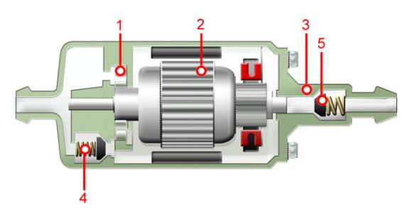
The low-pressure fuel pump draws fuel from the fuel tank and distributes it continuously to the high-pressure fuel pump. There are two low-pressure pump types. Figure 2: Electric fuel pump
|
|
| Operation | |
|
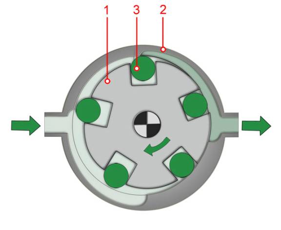
The electric fuel pump (Figure 2) can be fitted either in-tank or in-line. Besides fuel delivery, it also functions as a fuel cut-off if necessary. The electric fuel pump runs continuously, irrespective of the engine speed. The pump permanently delivers fuel to the injection system and an overflow valve allows excess fuel to flow back to the tank. When the ignition is on and the engine stopped, the delivery of fuel is prevented by a safety circuit. The electric fuel pump consists of a pump element, an electric motor and an end cover. The most commonly used pump element is the roller-cell pump (RCP). It's a positive-displacement pump (Figure 3) with free-moving slotted rotors (1) placed in the eccentric base plate (2). When the rotor rotates, the movable rollers (3) are forced outwards to the housing. This is caused by the effect of centrifugal force and fuel pressure. The rollers now act as rotating seals, creating a chamber. The electric motor ensures that the slotted rotor rotates continuously. Once the kidney-shaped inlet opening is closed, the volume of the chamber reduces continuously. This causes the pumping action. Figure 3: Roller-cell pump
The end cover contains the electrical connections and the pressure-side fuel outlet. A non-return valve is included to prevent the fuel lines from emptying when the fuel pump has switched off. |
|
| Operation | |
|
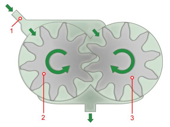
The gear fuel pump (Figure 4) is directly attached to the engine or is integrated in the high-pressure pump. It is mainly driven via a coupling, gearwheel or toothed belt. Fuel delivery depends on engine speed and is controlled by the throttle on the suction side or by means of an overflow valve on the pressure side. The pump consists of two engaging rotating gearwheels. The fuel is transported from suction to pressure side in the tooth spaces. The contact surface between the gearwheels functions as a seal and prevents the fuel from flowing back. When the engine has run dry or before the first start, the fuel system needs to be bled. Installing a hand pump directly on the gear pump or the low-pressure lines can facilitate this. Figure 4: Gear pump
|
|